Rectangular Patch Antenna Design Equations
Table of Contents Table of Contents 1 Introduction 2 Chapter 1: Single Element Microstrip Antenna 3. Triangular), is considered. Rectangular microstrip antenna design is based on transmission line model, while circular and triangular microstrip antenna designs are. To design a rectangular microstrip patch antenna one must go through the. The Microstrip Patch Antenna Calculation Process. Step 1: Calculation of the Width (W) - Step 2: Calculation of the Effective Dielectric Constant. This is based on the height, dielectric constant of the dielectric and the calculated width of the patch antenna. Patch Antenna Menu All of the parameters in a rectangular patch antenna design ( L, W, h, permittivity) control the properties of the antenna. As such, this page gives a general idea of how the parameters affect performance, in order to understand the design process.
- Rectangular Patch Antenna Design Equations Worksheet
- Design Equations For Patch Antenna Coax
- Patch Antenna Design
This tool calculates the dimensions of the microstrip patch antenna given the desired operating frequency.
Oregon 1000 kilometers rar. Oregon 1000 Kilometers Rar Files The Best Free Online Games at 108GAME.com. Awesome action games, puzzle games, adventure games, multiplayer games, skill games & best action games. Most of the information for completing the tables should be available in the files of the. 12 and 24 hours PW 2M of upper ran.-e linit rar.je. Region population.
Rectangular Patch Antenna Design Equations Worksheet

Outputs
Overview
A microstrip patch antenna is one of the most popular microwave antennas. This tool is designed to calculate the correct dimensions of a microstrip patch antenna if the operating frequency and the dielectric constant of the material used, is known. If the dielectric constant of the material is not known, you can choose to put in the velocity of propagation of the signal instead.
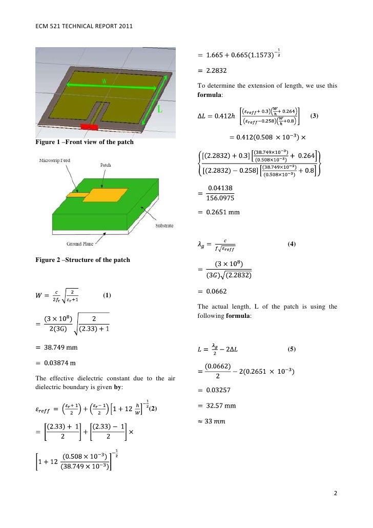
The length and width of the microstrip patch antenna can be calculated using the formulas below.
Equations
$$W = frac{c}{2f_{0}sqrt{frac{epsilon_{R}+1}{2}}}$$
$$L = frac{c}{2f_{0}sqrt{epsilon_{eff}}}-0.824hleft(frac{(epsilon_{eff}+0.3)(frac{W}{h}+0.264)}{(epsilon_{eff}-0.258)(frac{W}{h}+0.8)}right)$$
Where:
$$W$$ = width of the microstrip patch antenna
$$L$$ = length of the microstrip patch antenna
$$epsilon_{R}$$ = dielectric constant
$$epsilon_{eff} = frac{epsilon_{R}+1}{2} + frac{epsilon_{R}-1}{2}left[frac{1}{sqrt{1+12(frac{h}{W})}}right]$$
Applications
In recent years, the use of microstrip patch antennas have increased because of the inherent advantages. Together, with the increasing number of its users is the continuation of developing the method for more applications.
Design Equations For Patch Antenna Coax
Microstrip patch antennas gains an advantage over other microwave antennas in the area of portability as these antennas are lighter, and don't take much space. Another advantage of the microstrip patch antenna is the low cost involved and relative ease in manufacturing.
Patch Antenna Design
In terms of its performance, the microstrip patch antennas can provide dual and circular polarizations and can be operated using two frequencies. Other features of this antenna include frequency agility, feedline flexibility, wide bandwidth, omnidirectional patterning and beam scanning.
Further Reading
| 1. Introduction, Parameters and Fields of Microstrip Antennas 2. Bandwidth and Fringing Fields 3. Feeding Methods for Patch Antennas 4. Tradeoffs and Design Parameters of Microstrip Antennas 5. Video Simulation of Transient Fields Under a Microstrip Antenna 6. Planar Inverted-F Antennas (PIFAs) 7. Video Introduction and Analysis of Patch/Microstrip Antennas |
|